Drains and Basins
![]() Used to place floor drains and
basins, serving as terminator fittings used for water sewage.
Used to place floor drains and
basins, serving as terminator fittings used for water sewage.
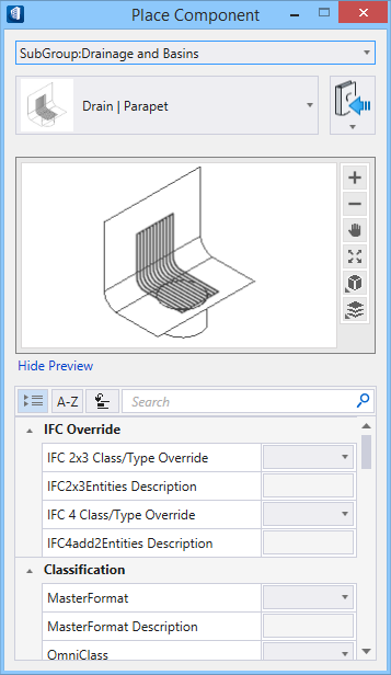
Selecting a fitting from the ribbon panel activates the Place Component settings dialog, where you can manage the schema parameters (DG instance properties). Also, the contextual Placement tab appears on the ribbon, that provides placement settings options for the currently selected fitting.
The generic placement settings, along with the unique set of dimensional and data parameters from the datagroup system provide the core workflow used to accurately position mechanical components within a system.
Component categories
A floor drain fitting with a removable plug that is found in a roughed in waste system. A floor drain fitting is designed with a removable plug or grill helps keep clear any type of debris that could cause any type of stoppage in the water drain lines. Floor drains are usually placed at the connection point between the sewer lines and the drain lines where the base is located of a vertical stack and at all places were the pipe direction changes at about 90°.
A floor drain is usually made up of two parts, a female thread adapter and a threaded male floor drain cone. The portion of thread adapter that sticks out of the wall determines how it is attached to the piping in the wall and the actual wall thickness. Multi-port floor drains: 4-, 5-, 6-way are suitable to drain in more standing water.
Floor trough fitting is uniquely designed and pitched to keep water and liquids draining rather than pooling. The number of bars sets the grill dimension for optimum draining and moderate clogging. Floor Drains’ properties are unique to the fitting. The properties for round floor drain (cleanout) are simply to define cone dimensions, grill size and the end type. The floor trough properties design the fitting size and capacity suitable a load class and gain sufficient clearance between bars to permit fluid and block potential clogs. The mounting height and flange properties set versatile flange that mounts directly to sub floors.
Notable Properties
- Connection End Type – The end conditions of fittings are set to flange, male or female connections with full dimensional control by setting the End Type property. Also, the two ends are independent, and may have different connections. For example, the value fl-2;fe-.13 creates a flange at End1 with size 2, and a female connection at End2 with a clearance of .13.
- Flange Size – The flange size and offset relative to the basket dimension control overall safety aspects of the floor trough.
The list of fittings available in Drains and Basins group is compiled in the Drains and Basins types topic.